

A Channel Phase Self-compensation Method for Active-Integrated Arrays
-
摘要: 有源电路与天线的无缝集成能有效改善链路性能与集成度。当前,有源集成天线主要是在保证天线辐射性能的前提下调控天线阻抗特性使其与有源晶体管实现直接匹配。天线复阻抗特性对有源通道的相位响应影响,及其在有源集成相控阵列中的应用还未进行充分分析。有源电路与天线的无缝集成能有效改善链路整体性能与集成度。该文提出一种用于有源集成阵列的通道相位自补偿方法。每个有源通道中的有源晶体管与辐射阵元需直接集成,即晶体管漏极输出端的负载阻抗与辐射阵元的输入阻抗匹配。通过在恒定有源增益下对该负载阻抗(复阻抗)求解,可以得到有源通道相位响应与负载阻抗的具体映射关系。进而针对各通道间对于移相范围的具体要求,选择合适的负载阻抗作为相应辐射阵元的输入阻抗,便可以在不采用外部移相结构的情况下,对每个通道施加一组相位分布,用以控制初始波束指向或者共形阵列中阵元之间波程差补偿等应用。该文设计、加工和测试了一个具有初始波束指向的有源集成相控阵天线设计实例,验证了该方法的有效性。Abstract:
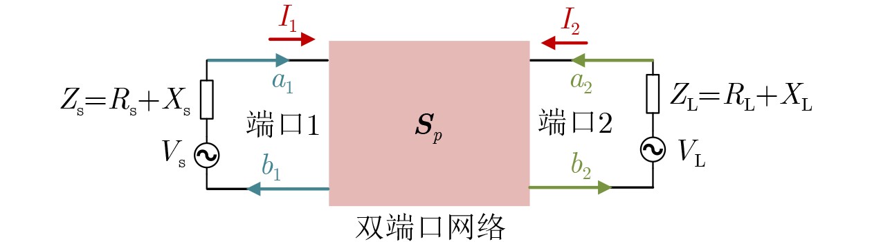
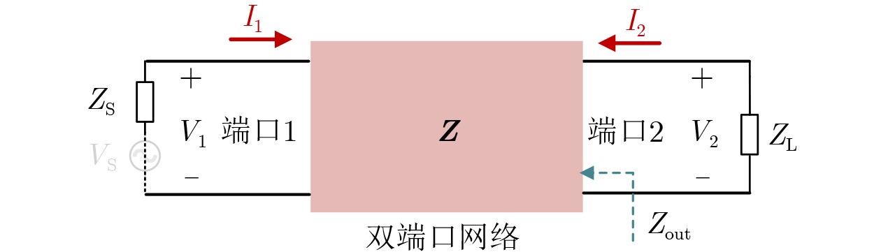
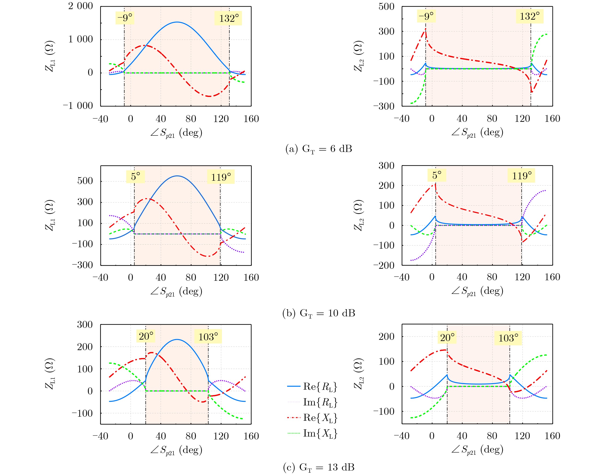
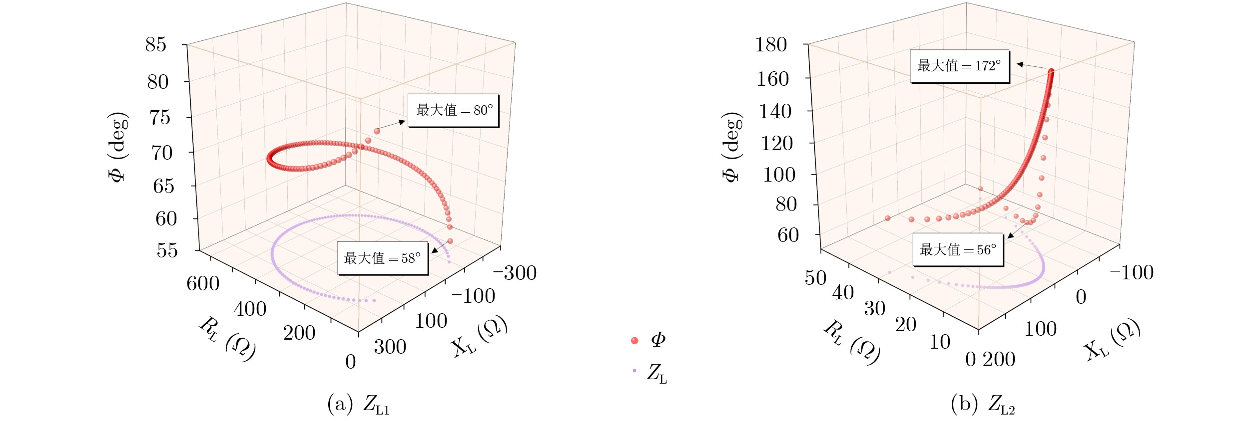
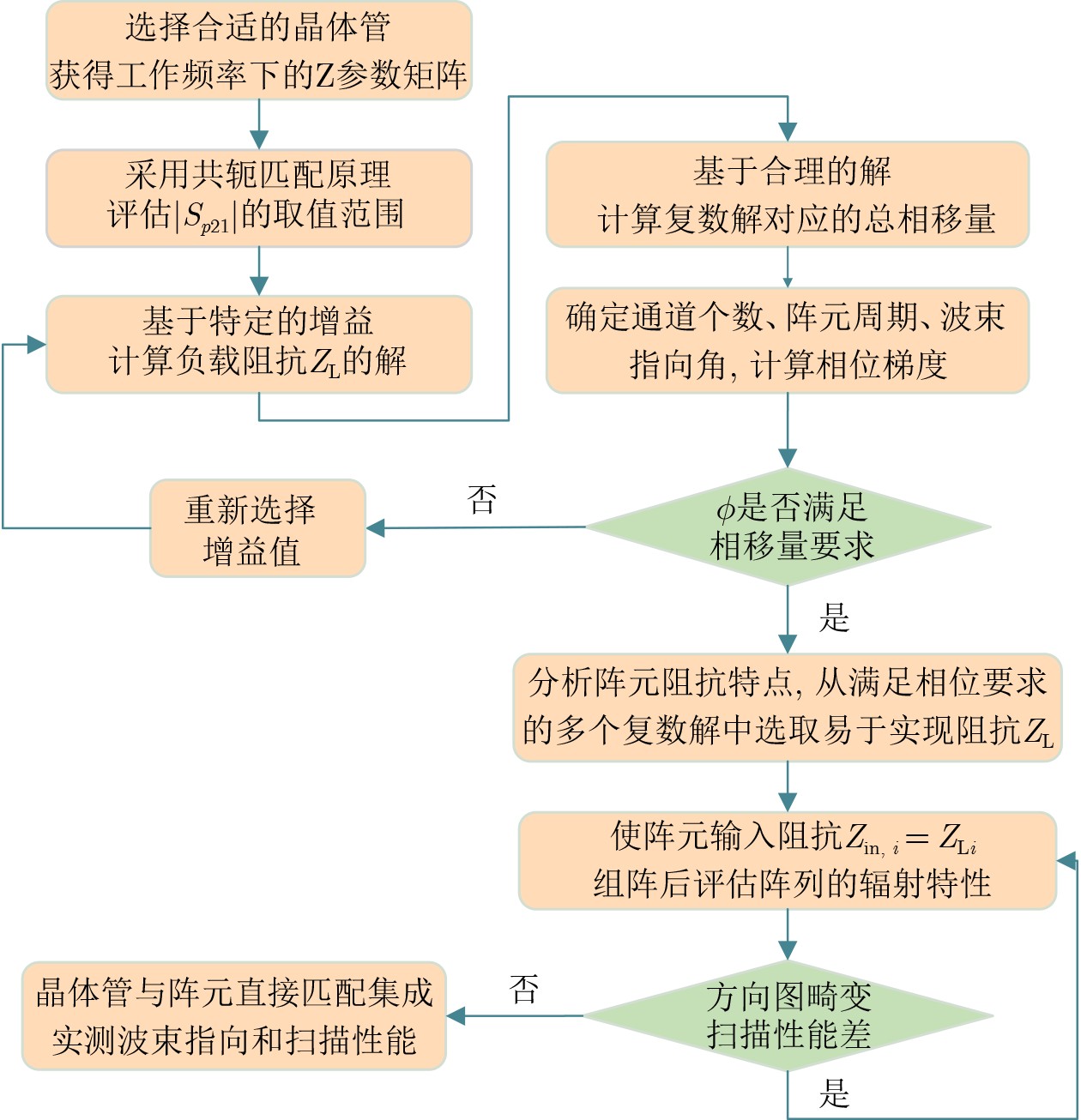
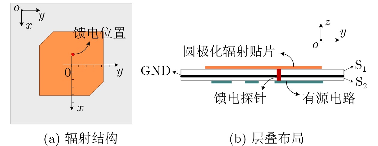
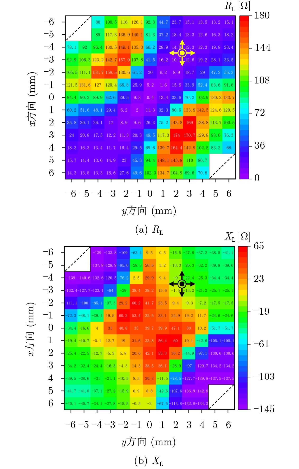
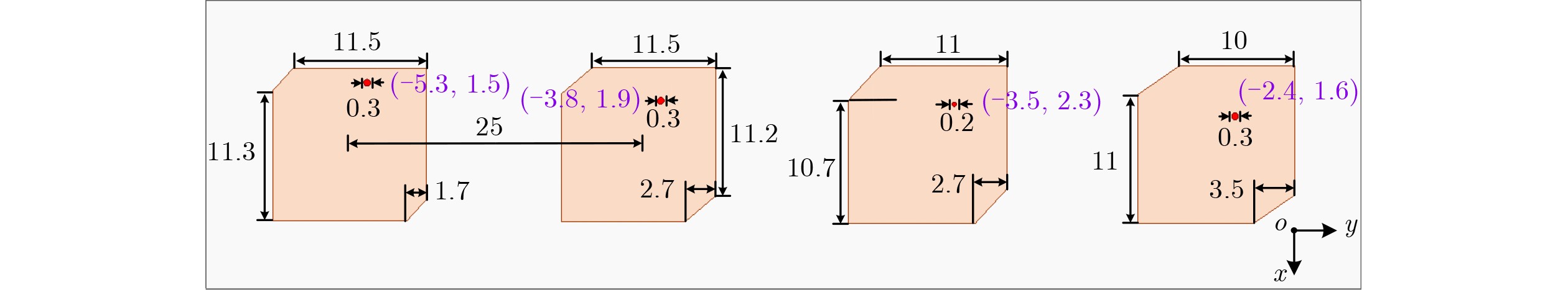
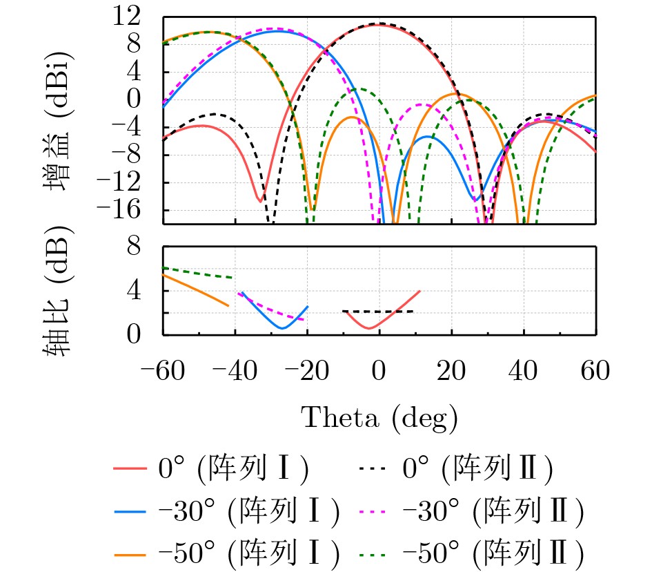
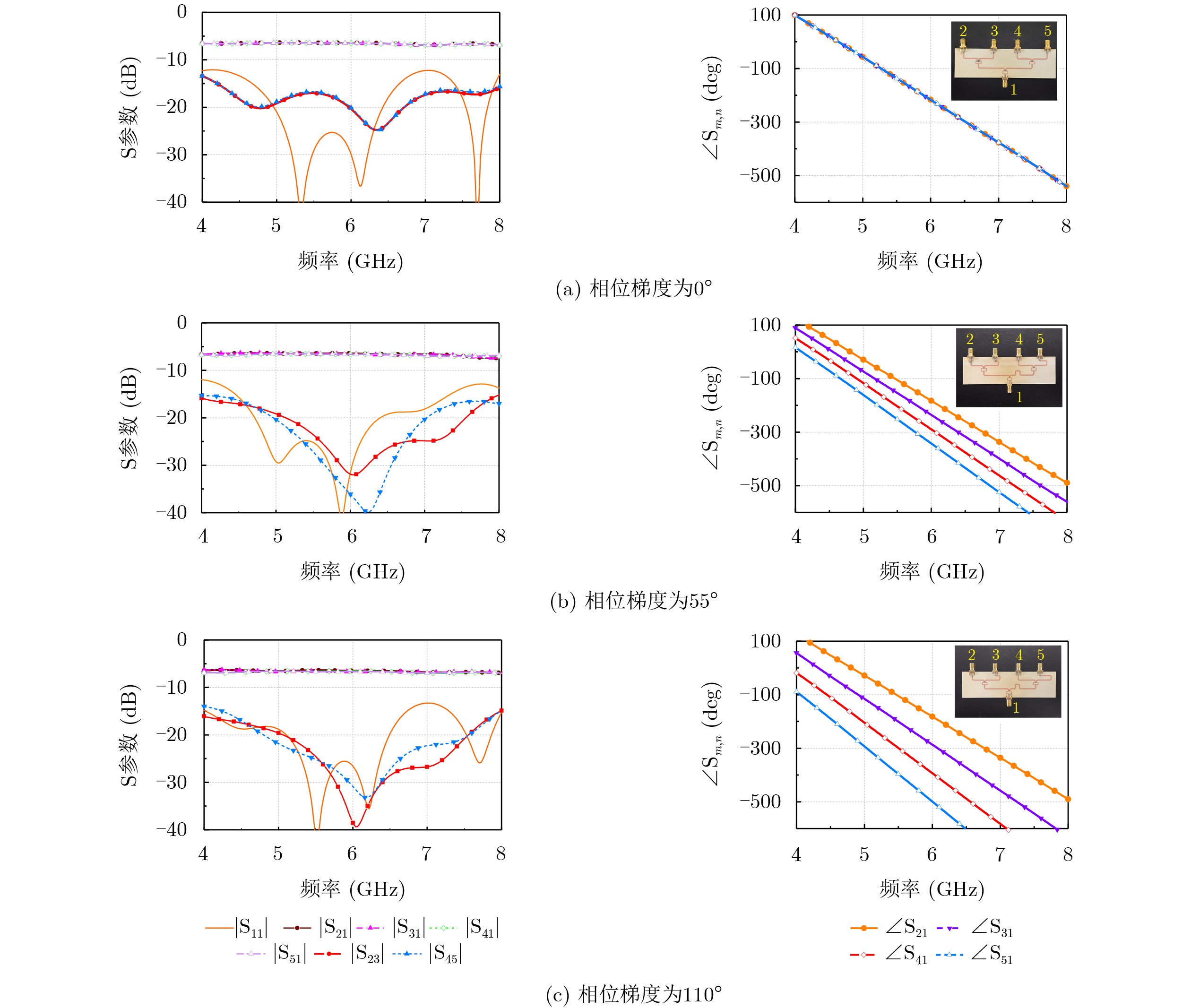
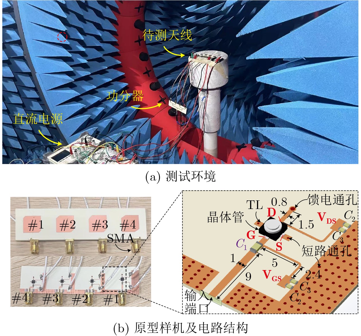
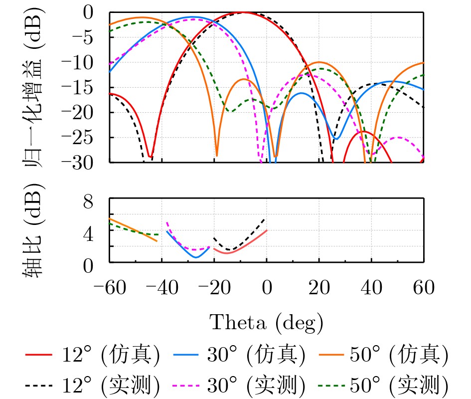
The seamless integration of active circuitry and antennas can effectively improve link performance and system integration. At present, active-integrated antennas are mainly designed by adjusting the antenna impedance while maintaining the desired radiation characteristics to achieve direct matching with active transistors. However, the effect of the antenna’s complex impedance on the phase response of the active channel, as well as its potential application in active-integrated phased arrays, has not been thoroughly studied. This paper proposes a channel phase self-compensation method for active-integrated arrays. For each active channel, the active transistor is directly integrated with the radiating element, where the load impedance at the transistor drain is matched to the input impedance of the antenna element. Under a constant active gain, the required complex load impedance is solved to establish an explicit mapping between the phase response of each active channel and its corresponding load impedance. According to the phase-shift requirements among array channels, appropriate load impedances are selected as the input impedances of the corresponding radiating elements. This approach applies a predefined phase distribution to each channel without using external phase-shifting structures. It can control the initial beam direction or compensate for the path difference between elements in conformal arrays. An active-integrated phased-array antenna with a preset beam direction is designed as a demonstration example to verify the effectiveness of the proposed method. The method provides an efficient design approach for next-generation active-integrated arrays. Objective In the traditional design approach, active circuit channels and antenna arrays are matched to 50 Ω before interconnection. This configuration occupies considerable physical space and limits system-level integration. In addition, insertion loss in passive matching networks and mismatch loss at the interconnections reduce overall link performance. Direct co-integration of active circuitry and antenna elements can address these limitations. However, multi-channel active-integrated antenna arrays often require one or multiple superimposed phase distributions across the channels to satisfy different application requirements, such as initial beam offset in fuze systems, wavefront compensation in conformal active phased arrays, and wide-angle beam scanning. These phase gradients are typically realized through backend phase-shifting networks. In this work, the complex impedance characteristics of the antenna are adjusted when it is directly integrated with the active circuitry. The phase response of the active-integrated channels can therefore be tuned within a certain range without using complex matching networks or additional phase shifters. This strategy reduces the complexity and performance requirements of the backend phase-shifting network. The advantages are more evident in millimeter-wave, high-frequency, and terahertz systems, where the available phase-shift range of phase shifters is limited. Methods Phase self-compensation of the active channels is achieved through the direct integration of the active transistor and the radiating element. In this configuration, the drain output of the transistor is directly connected to the input of the radiating element, and impedance transformation is realized within the antenna element. The proposed method includes three main steps. (1) The active transistor is first modeled as a two-port network. By evaluating the antenna element’s complex impedance as the load on different constant-gain circles, the mapping between the phase response of the active channel and the load impedance is established. The achievable phase-shift range of the active channel is then determined. (2) According to the required phase-shift distribution among the array channels, suitable combinations of active gain and corresponding complex load impedances (not unique) are selected. These combinations are not unique. (3) The realizability of the selected impedances is examined according to the characteristics of the radiating element. The impedance values with the highest feasibility are implemented by optimizing the radiating element, which includes fine adjustment of its geometry and feed position to meet the target impedance. When the radiating element is modified, particularly for circularly polarized elements, desirable radiation characteristics must also be preserved, including good axial ratio and beam-scanning performance. Results and Discussions The proposed phase self-compensation mechanism enables the array to achieve initial beam pointing and compensate for path-length differences caused by special array geometries, such as conformal or curved surfaces, without using additional phase-shifting structures. Therefore, the performance requirements of the backend phase-shifting network in active phased arrays can be reduced. To verify the effectiveness of the proposed method, a 1×4 circularly polarized active-integrated linear array ( Fig. 9 ) is designed and demonstrated. Based on channel-level impedance calculations (Fig. 6 ) and an analysis of the antenna-element impedance characteristics (Fig. 8 ), a phase gradient of 38° between adjacent channels is synthesized and applied to the circularly polarized active-integrated array. Without degrading the circular polarization performance and without external phase-shifting circuitry, the initial beam direction of the active-integrated phased array is shifted to the desired angle of θ0 = 12° (Fig. 13 ). The phase self-compensation design does not degrade the beam-scanning capability of the array. After an additional phase gradient is applied for beam steering, the array achieves a scanning range of up to 50°. The gain reduction remains within 2 dB relative to the initial pointing direction, and the axial ratio remains below 4 dB throughout the scanning range.Conclusions Within the framework of active-integrated arrays, this work uses the phase-tuning effect produced by the complex impedance at the antenna port when the radiating element is directly matched to the active transistor. A desired phase-gradient distribution can therefore be synthesized among the channels of an active-integrated phased array within an achievable range. This capability enables compensation for required phase distributions, such as preset beam direction and path-length equalization in conformal-array applications, without relying on additional phase shifters. Therefore, the complexity and performance requirements of the backend phase-shifting circuitry are reduced. The effectiveness of the proposed method is validated through a multi-channel circularly polarized active-integrated phased-array prototype with a preset beam direction. Both full-wave simulations and experimental measurements confirm that the phase self-compensation mechanism provides the required initial beam pointing while preserving beam-scanning capability and polarization performance. This study provides a new approach for the design of high-efficiency next-generation active-integrated phased arrays. -
Key words:
- Active integration /
- Phased array /
- Phase compensation /
- Beam scanning /
- Circular polarization
-
表 1 1×4规模阵列中各有源通道依次实现的相移量及负载阻抗
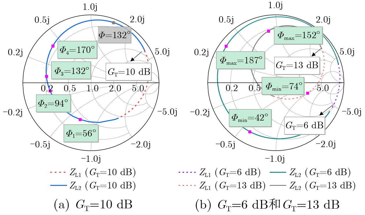
通道1 通道2 通道3 通道4 相移量Φ 56° 94° 132° 170° ∠Sp21 116° 112° 108 99° tan–1(XL/RL) –60° –18° 24° 71° ZL(Ω) 21–j35 11.9–j4 10+j4.5 7+j20  下载: 导出CSV
-
[1] 石涵琛, 杨闯, 彭木根. 6G太赫兹通信: 架构、技术与挑战[J]. 电波科学学报, 2024, 39(3): 395–412. doi: 10.12265/j.cjors.2023130.SHI Hanchen, YANG Chuang, and PENG Mugen. Terahertz communication for 6G: Architectures, technologies and challenges[J]. Chinese Journal of Radio Science, 2024, 39(3): 395–412. doi: 10.12265/j.cjors.2023130. [2] KIM W, ISKANDER M F, and PALMER W D. An integrated phased array antenna design using ferroelectric materials and the continuous transverse stub technology[J]. IEEE Transactions on Antennas and Propagation, 2006, 54(11): 3095–3105. doi: 10.1109/TAP.2006.883994. [3] XIA Xiaoyue, YU Chao, WU Fan, et al. Millimeter-wave phased array antenna integrated with the industry design in 5G/B5G smartphones[J]. IEEE Transactions on Antennas and Propagation, 2023, 71(2): 1883–1888. doi: 10.1109/TAP.2023.3234173. [4] 洪伟, 徐俊, 陈继新, 等. 面向6G的最优和次优毫米波大规模波束成形阵列架构[J]. 电子与信息学报, 2025, 47(8): 2405–2415. doi: 10.11999/JEIT250109.HONG Wei, XU Jun, CHEN Jixin, et al. Optimal and suboptimal architectures of millimeter-wave large-scale arrays for 6G[J]. Journal of Electronics & Information Technology, 2025, 47(8): 2405–2415. doi: 10.11999/JEIT250109. [5] WARNICK K F. Noise figure of an active antenna array and receiver system[J]. IEEE Antennas and Wireless Propagation Letters, 2022, 21(8): 1607–1609. doi: 10.1109/LAWP.2022.3175146. [6] LIN Qingqing. XU Jun, CHEN Kai, et al. A single-board integrated millimeter-wave asymmetric full-digital beamforming array for B5G/6G applications[J]. Engineering, 2024, 41(10): 38–53. doi: 10.1016/j.eng.2024.04.013. [7] 李旭光, 刘兵, 傅海鹏, 等. 130 GHz CMOS有源矢量合成移相器[J]. 电子与信息学报, 2021, 43(6): 1559–1564. doi: 10.11999/JEIT210071.LI Xuguang, LIU Bing, FU Haipeng, et al. A 130 GHz CMOS active vector-modulation phase shifter[J]. Journal of Electronics & Information Technology, 2021, 43(6): 1559–1564. doi: 10.11999/JEIT210071. [8] CHEN Kai, XU Jun, TANG Siyuan, et al. Millimeter-wave active beam-tilted phased array modules and seamless integration design with ultrawideband sub-6 GHz antenna for future V2X applications[J]. IEEE Transactions on Antennas and Propagation, 2025, 73(5): 2737–2753. doi: 10.1109/TAP.2024.3518064. [9] 冯孔豫. 天线波束相位理论[J]. 电子与信息学报, 1984, 6(2): 96–106.FENG Kongyu. Phase theory of antenna beam[J]. Journal of Electronics & Information Technology, 1984, 6(2): 96–106. [10] LOW K K W, ZIHIR S, KANAR T, et al. A 27–31-GHz 1024-element Ka-band SATCOM phased-array transmitter with 49.5-dBW peak EIRP, 1-dB AR, and ±70° beam scanning[J]. IEEE Transactions on Microwave Theory and Techniques, 2022, 70(3): 1757–1768. doi: 10.1109/TMTT.2021.3139911. [11] FANG Shigang and QU Shiwei. Broadband wide-scanning large-curvature cylindrical conformal dipole array antenna with low-scattering characteristics[J]. IEEE Transactions on Antennas and Propagation, 2024, 72(8): 6437–6447. doi: 10.1109/TAP.2024.3417293. [12] LI Jiashang, QU Shiwei, FENG Pengyu, et al. Dual-band omnidirectional scanning conical conformal phased array antenna[J]. IEEE Antennas and Wireless Propagation Letters, 2024, 23(12): 4768–4772. doi: 10.1109/LAWP.2024.3470792. [13] LIAO Wanchun, MAASKANT R, EMANUELSSON T, et al. A directly matched PA-integrated K-band antenna for efficient mm-wave high-power generation[J]. IEEE Antennas and Wireless Propagation Letters, 2019, 18(11): 2389–2393. doi: 10.1109/LAWP.2019.2937235. [14] NALLANDHIGAL S N, BAYAT-MAKOU N, and WU Ke. Scalable planar active array antenna integrated with distributed amplifying transistors for high-power applications[J]. IEEE Transactions on Microwave Theory and Techniques, 2021, 69(7): 3425–3437. doi: 10.1109/TMTT.2021.3073405. [15] VILENSKIY A R, LIAO Wanchun, MAASKANT R, et al. Co-design and validation approach for beam-steerable phased arrays of active antenna elements with integrated power amplifiers[J]. IEEE Transactions on Antennas and Propagation, 2021, 69(11): 7497–7507. doi: 10.1109/TAP.2021.3076255. [16] EMADEDDIN A and JONSSON B L G. Wide scan, active K-band, direct-integrated phased array for efficient high-power Tx-generation[J]. IEEE Transactions on Antennas and Propagation, 2023, 71(9): 7579–7584. doi: 10.1109/TAP.2023.3281075. [17] LIAO Wanchun, VILENSKIY A R, MAASKANT R, et al. mmWave metal bowtie slot array element integrating power amplifier MMIC via on-chip probe to enhance efficiency and bandwidth[J]. IEEE Transactions on Antennas and Propagation, 2022, 70(9): 8110–8121. doi: 10.1109/TAP.2022.3177524. [18] NALLANDHIGAL S N and WU Ke. Analysis and impact of port impedances on two-port networks and its application in active array antenna developments[J]. IEEE Transactions on Microwave Theory and Techniques, 2021, 69(4): 2357–2370. doi: 10.1109/TMTT.2021.3061441. [19] POZAR D M. Microwave Engineering[M]. 4th ed. Hoboken, USA: Wiley, 2011. [20] MAILLOUX R J. Phased Array Antenna Handbook[M]. 2nd ed. Norwood, USA: Artech House, 2005. -


图(13) / 表(1)
计量
- 文章访问数: 198
- HTML全文浏览量: 96
- PDF下载量: 23
- 被引次数: 0
 下载:
下载:
